On the Wire⚓︎
Difficulty:
Direct link: On the Wire
Objective⚓︎
Request
Help Evan next to city hall hack this gnome and retrieve the temperature value reported by the I²C device at address 0x3C. The temperature data is XOR-encrypted, so you’ll need to work through each communication stage to uncover the necessary keys. Start with the unencrypted data being transmitted over the 1-wire protocol.
Evan Booth
So here's the deal - there are some seriously bizarre signals floating around this area.
Not your typical radio chatter or WiFi noise, but something... different.
I've been trying to make sense of the patterns, but it's like trying to build a robot hand out of a coffee maker - you need the right approach.
Think you can help me decode whatever weirdness is being transmitted out there?
You know what happens to electronics in extreme cold? They fail. All my builds, all my robots, all my weird coffee-maker contraptions—frozen solid. We can't let Frosty turn this place into a permanent deep freeze.
Hints⚓︎
Protocols
Key concept - Clock vs. Data signals:
Some protocols have separate clock and data lines (like SPI and I2C) For clocked protocols, you need to sample the data line at specific moments defined by the clock The clock signal tells you when to read the data signal For 1-Wire (no separate clock):
Information is encoded in pulse widths (how long the signal stays low or high) Different pulse widths represent different bit values Look for patterns in the timing between transitions For SPI and I2C:
Identify which line is the clock (SCL for I2C, SCK for SPI) Data is typically valid/stable when the clock is in a specific state (high or low) You need to detect clock edges (transitions) and sample data at those moments Technical approach:
Sort frames by timestamp Detect rising edges (0→1) and falling edges (1→0) on the clock line Sample the data line's value at each clock edge
Bits and Bytes
Critical detail - Bit ordering varies by protocol:
MSB-first (Most Significant Bit first):
SPI and I2C typically send the highest bit (bit 7) first When assembling bytes: byte = (byte << 1) | bit_value Start with an empty byte, shift left, add the new bit LSB-first (Least Significant Bit first):
1-Wire and UART send the lowest bit (bit 0) first When assembling bytes: byte |= bit_value << bit_position Build the byte from bit 0 to bit 7 I2C specific considerations:
Every 9th bit is an ACK (acknowledgment) bit - ignore these when decoding data The first byte in each transaction is the device address (7 bits) plus a R/W bit You may need to filter for specific device addresses Converting bytes to text:
String.fromCharCode(byte_value) // Converts byte to ASCII character
On Rails
Stage-by-stage approach
- Connect to the captured wire files or endpoints for the relevant wires.
- Collect all frames for the transmission (buffer until inactivity or loop boundary).
- Identify protocol from wire names (e.g., dq → 1-Wire; mosi/sck → SPI; sda/scl → I²C).
- Decode the raw signal:
- Pulse-width protocols: locate falling→rising transitions and measure low-pulse width.
- Clocked protocols: detect clock edges and sample the data line at the specified sampling phase.
- Assemble bits into bytes taking the correct bit order (LSB vs MSB).
- Convert bytes to text (printable ASCII or hex as appropriate).
- Extract information from the decoded output — it contains the XOR key or other hints for the next stage.
- Repeat Stage 1 decoding to recover raw bytes (they will appear random).
- Apply XOR decryption using the key obtained from the previous stage.
- Inspect decrypted output for next-stage keys or target device information.
- Multiple 7-bit device addresses share the same SDA/SCL lines.
- START condition: SDA falls while SCL is high. STOP: SDA rises while SCL is high.
- First byte of a transaction = (7-bit address << 1) | R/W. Extract address with address = first_byte >> 1.
- Identify and decode every device’s transactions; decrypt only the target device’s payload.
- Print bytes in hex and as ASCII (if printable) — hex patterns reveal structure.
- Check printable ASCII range (0x20–0x7E) to spot valid text.
- Verify endianness: swapping LSB/MSB will quickly break readable text.
- For XOR keys, test short candidate keys and look for common English words.
- If you connect mid-broadcast, wait for the next loop or detect a reset/loop marker before decoding.
- Buffering heuristic: treat the stream complete after a short inactivity window (e.g., 500 ms) or after a full broadcast loop.
- Sort frames by timestamp per wire and collapse consecutive identical levels before decoding to align with the physical waveform.
Solution⚓︎
Initial access and signal source⚓︎
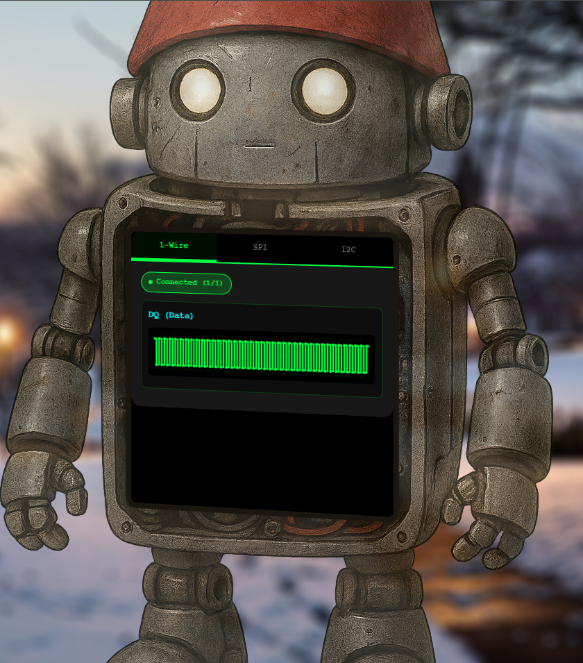
After clicking the objective terminal, a webpage shows the signal dashboard with the protocol and the wires used by the protocol. The default one shows the waves of the DQ wire for the 1-Wire protocol.
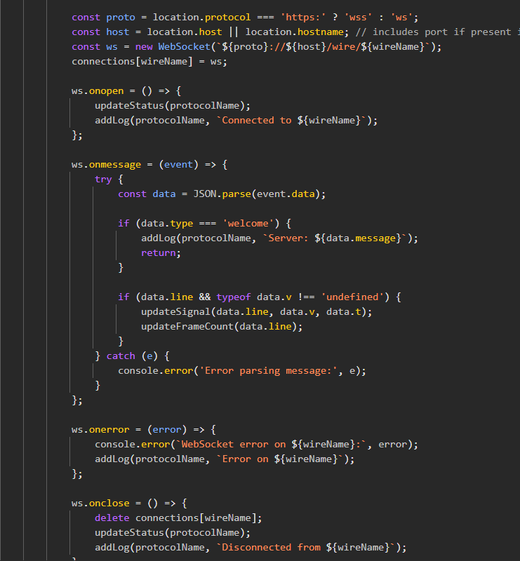
I found in the website source code that the data of every wire's graph comes from a websocket.
1-Wire stage⚓︎
1-Wire uses a single data line (DQ) with no separate clock, so bits are encoded by the width of low pulses. I noticed that short low pulses are 6 µs and represent a bit 1 while long low pulses are 60 µs and represent a bit 0.
A voltage v reading 0 corresponds to "High" idle state, and 1 means the line is low.
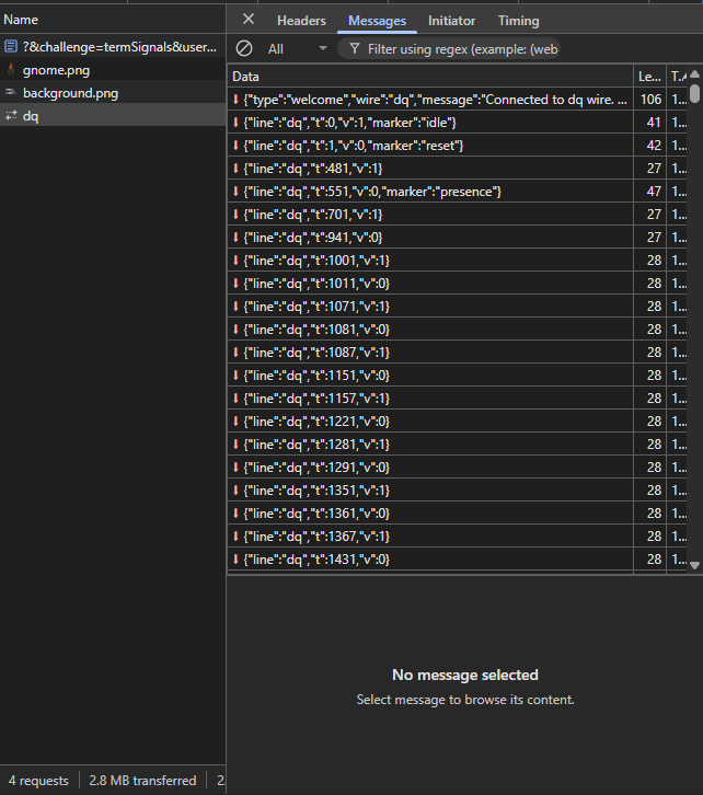
Under the message part of the devtools network section for the dq request, the data format is as follows:
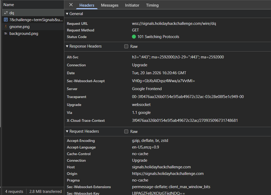
In DevTools, the websocket request header shows a secure websocket (wss) endpoint in use for live data.
So I wrote this python script to help decode the 1-Wire DQ stream.
Notes on how this works:
- The 1-Wire DQ line encodes bits by pulse width; short low pulses commonly mean '1' and long low pulses mean '0'.
- Each WebSocket message carries a voltage level
Vand a timestampt. - Pulse duration =
t - previous_t; 6 µs → bit 1, 60 µs → bit 0, anything else is discarded - On
{"Marker": "stop"}, the WebSocket closes and the collected bits are processed. - Bits are assembled LSB-first into bytes: the first observed bit becomes bit 0 of the byte.
- The resulting bytes are decoded as ASCII to produce the XOR key for the next stage.
Decoding script:
WebSocket stream
    │
    ▼
timestamp delta → pulse width
    │
    ▼
6 µs → bit 1,  60 µs → bit 0   (pulse-width decoding)
    │
    ▼
data_list  (stream of bits, others discarded)
    │
    ▼
bits_to_bytes() — 8 bits at a time, LSB-first
(byte |= bit << bit_index)
    │
    ▼
bytes → ASCII string  →  XOR key for next stage
| Decode 1-Wire | |
|---|---|
1 2 3 4 5 6 7 8 9 10 11 12 13 14 15 16 17 18 19 20 21 22 23 24 25 26 27 28 29 30 31 32 33 34 35 36 37 38 39 40 41 42 43 44 45 46 47 48 49 50 51 52 53 54 55 56 57 58 59 60 61 62 63 64 65 66 67 68 69 70 71 72 73 74 | |
The script helped to decrypt the sent data and get the XOR key icy.

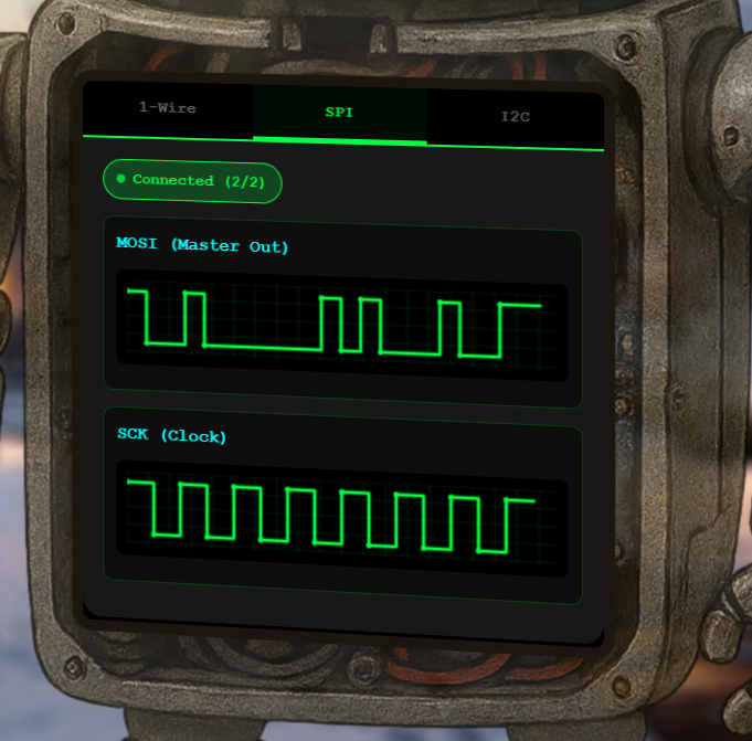
SPI stage⚓︎
SPI has a dedicated clock (SCK) and data line (MOSI). Data is sampled at specific clock signal. SPI transmits data MSB-first: the most significant bit (bit 7) of each byte is sent first, so bytes must be assembled by shifting left and OR-ing each new bit in.
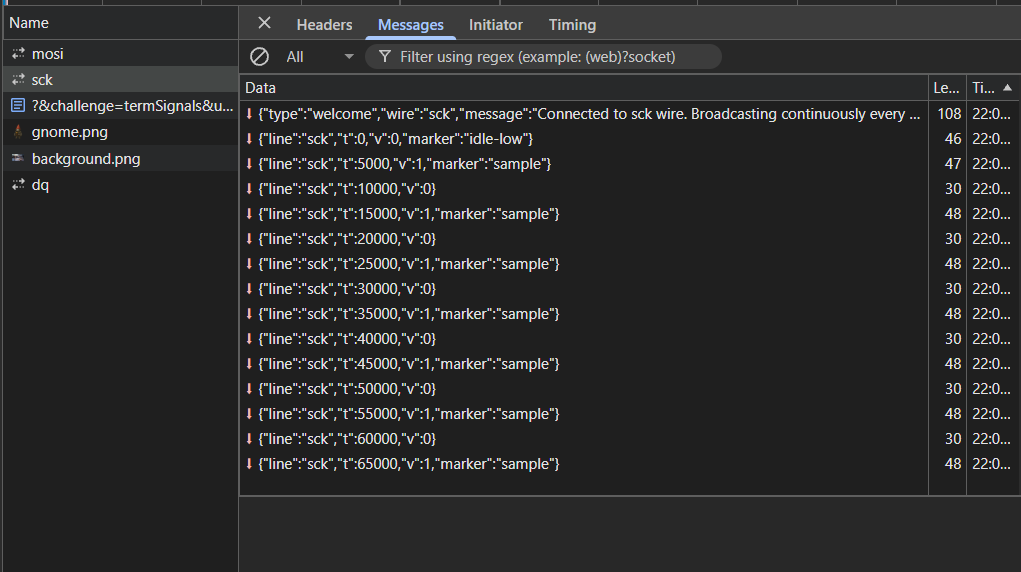
The SCK wire request in the network section of the DevTools shows how the clock data is formatted.
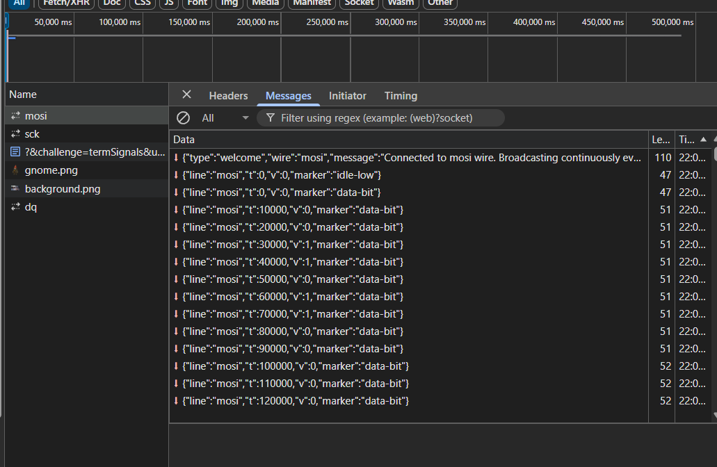
The MOSI wire request in the network section of the DevTools shows how the sample data is formatted.
I wrote this new python script to use the previously found xor key icy to decode the SPI data.
Notes on how SPI decoding works:
- Two WebSocket streams are collected: MOSI (
data-bit) and SCK (data-sample) - Streams close when the
"idle-low"marker is seen twice witht=0, indicating a full broadcast. - For each SCK sample event, the latest MOSI value with
t <= SCK timestampis picked one bit each clock edge. - Bits are assembled MSB-first into bytes: shift left and OR the sampled bit.
- Bytes are XOR-decrypted with the key from the 1-Wire stage to reveal the next key.
Decoding script:
Two WebSocket streams (MOSI and SCK)
    │
    ▼
Buffer until "idle-low" marker seen twice
    │
    ▼
For each SCK sample event:
  find latest MOSI value with t ≤ SCK timestamp
    │
    ▼
combined_samples  (one bit per clock edge)
    │
    ▼
bits_to_bytes_msb() — 8 bits at a time, MSB-first
(byte = (byte << 1) | bit)
    │
    ▼
XOR decrypt with key from 1-Wire stage
    │
    ▼
bytes → ASCII string  →  XOR key for next stage
| Decode SPI | |
|---|---|
1 2 3 4 5 6 7 8 9 10 11 12 13 14 15 16 17 18 19 20 21 22 23 24 25 26 27 28 29 30 31 32 33 34 35 36 37 38 39 40 41 42 43 44 45 46 47 48 49 50 51 52 53 54 55 56 57 58 59 60 61 62 63 64 65 66 67 68 69 70 71 72 73 74 75 76 77 78 79 80 81 82 83 84 85 86 87 88 89 90 91 92 93 94 95 96 97 98 | |
After sampling MOSI on SCK edges and assembling MSB-first bytes, the SPI payload decodes into the next XOR key bananza.
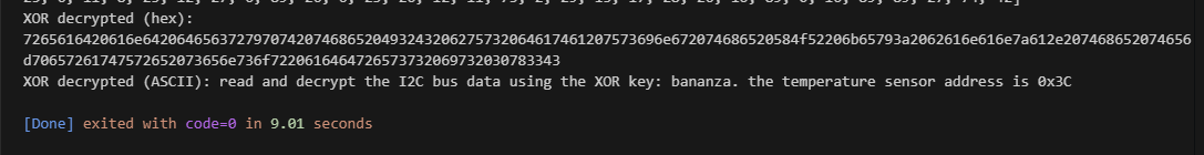
I2C stage⚓︎
I2C uses two lines: SCL for the clock and SDA for data. Multiple devices share the same bus, each identified by a 7-bit address. The bus signals bus activity through special conditions: a START condition is when SDA falls while SCL is high, and a STOP condition is when SDA rises while SCL is high.
The first byte of every I2C transaction carries the target device's 7-bit address in the upper 7 bits, plus a Read/Write flag in the lowest bit. Therefore, the raw address byte must be shifted right by one (first_byte >> 1) to recover the 7-bit address. After every byte of data the bus expects an ACK bit (a 9th clock pulse), which is a handshake and not part of the payload. Those ACK bits must be stripped out before assembling bytes.
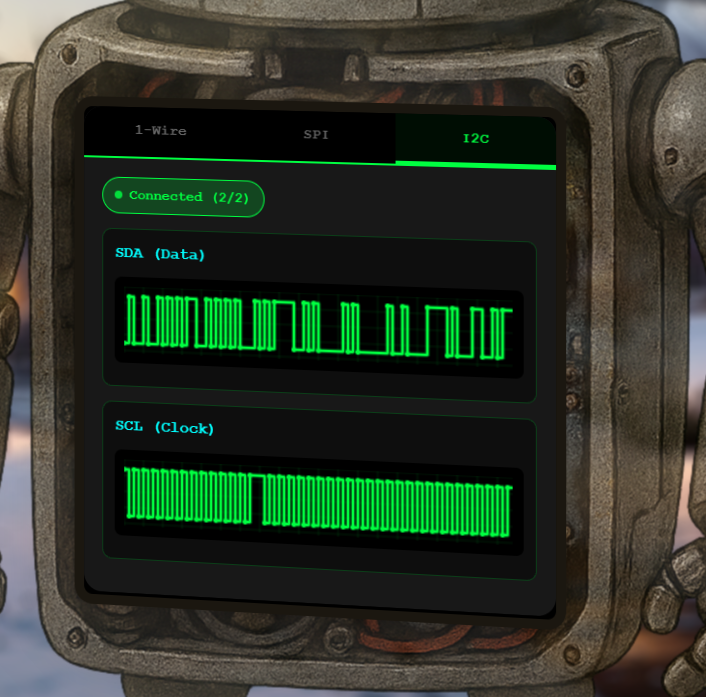
The SDA capture shows data changes aligned to SCL high periods.
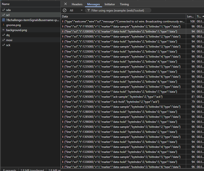
The SCL capture provides the clock edges for sampling SDA and counting ACK bits.
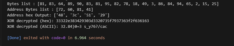
I wrote this python script to use the previously found XOR key bananza to decode the I2C data and found the temperature value 32.84.
Notes on how I2C decoding works (explanatory, non-code guidance):
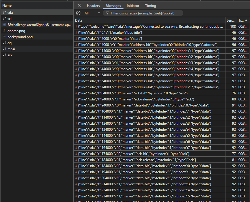
- Two WebSocket streams are collected: SDA (
"data-bit"or"address-bit") and SCL ("data-sample"or"address-sample") - Streams close when the
"bus-idle"marker is seen twice witht=0, indicating a full broadcast. - For each SCL sample event, the latest SDA value with
t <= SCL timestampis picked one bit each clock edge. - Address and data samples are kept separate during collection based on their marker types
- Address bits are decoded to locate the target device
0x3c - Data bits belonging to that transaction are extracted and assembled MSB-first into bytes
- Bytes are XOR-decrypted with the key from the SPI stage to reveal the temperature value.
Decoding script:
Two WebSocket streams (SDA and SCL)
    │
    ▼
Buffer until "bus-idle" marker seen twice
    │
    ▼
For each SCL sample event:
  find latest SDA value with t ≤ SCL timestamp
  separate into address_samples vs data_samples by marker type
    │
    ▼
decode_address() → identify transaction for device 0x3C
    │
    ▼
extract data bits belonging to that transaction
    │
    ▼
bits_to_bytes_msb() — 8 bits at a time, MSB-first
(byte = (byte << 1) | bit)
    │
    ▼
XOR decrypt with key from SPI stage ("bananza")
    │
    ▼
bytes → ASCII string  →  temperature value
| Decode I2C | |
|---|---|
1 2 3 4 5 6 7 8 9 10 11 12 13 14 15 16 17 18 19 20 21 22 23 24 25 26 27 28 29 30 31 32 33 34 35 36 37 38 39 40 41 42 43 44 45 46 47 48 49 50 51 52 53 54 55 56 57 58 59 60 61 62 63 64 65 66 67 68 69 70 71 72 73 74 75 76 77 78 79 80 81 82 83 84 85 86 87 88 89 90 91 92 93 94 95 96 97 98 99 100 101 102 103 104 105 106 107 108 109 110 111 112 113 114 115 116 117 118 119 120 121 122 123 124 125 126 127 128 129 130 131 132 133 134 135 136 137 138 139 140 141 142 143 144 145 146 147 148 | |
Once the I2C transaction for address 0x3C was decoded and XOR-decrypted, the temperature value appeared.
Wrap-up and completion⚓︎
The objective completion screen confirms the decoded I2C temperature result was accepted.
Answer
32.84
Response⚓︎
Evan Booth
Nice work! You cracked that signal encoding like a pro.
Turns out the weirdness had a method to it after all - just like most of my builds!